 |
 |
 |
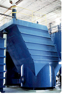 HEI Inclined Plate Clarifiers Use Gravity & Innovative Engineering.
A gravity clarifier is the most economical method
of removing solids from liquid because natural gravity is the source of
energy and it is free. A clarifier simply provides a non-turbulent zone
where heavier than liquid solids, suspended by turbulence, are given
sufficient time to settle to a quiescent surface. The HEI inclined
plate clarifiers are compact units with multiple layers of settling
area utilizing less than 25% of the floor space required by
conventional clarifiers.
Principle of Horizontal Clarifier |
A particle carried forward by the velocity of the
liquid flow must settle at a rate that allows it to reach the bottom
before passing through the clarifier. Thus, particles beginning at a
point "a" must traverse some route lying between ab and ab' in order to
avoid being carried over the outlet.
If V is the horizontal velocity of the liquid, S
the solids particle vertical settling velocity, L the length of the
settling device, and D its depth, then particles entering at point A
will settle to the bottom of the device only if V does not exceed:
S(L/D)
Since Vmax / S = L / D then, Vmax = S (L / D)
Therefore, the velocity at which a horizontal
clarifying device may be operated successfully is directly proportional
to its length and inversely proportional to its depth.
 This
analysis applies to multiple horizontal plate units also. The spacing
between plates is usually a few inches as opposed to a depth of several
feet in a horizontal tank; therefore, "settling-out" times are
dramatically reduced. The flow must be non-turbulent to prevent settled
solids from being reentrained within the moving liquid. Small plate
spacing and a large surface area permits laminar flow at higher
velocities than large horizontal tanks would allow.
This
analysis applies to multiple horizontal plate units also. The spacing
between plates is usually a few inches as opposed to a depth of several
feet in a horizontal tank; therefore, "settling-out" times are
dramatically reduced. The flow must be non-turbulent to prevent settled
solids from being reentrained within the moving liquid. Small plate
spacing and a large surface area permits laminar flow at higher
velocities than large horizontal tanks would allow.Horizontal clarifying devices become self-flushing
if they are inclined at an angle which exceeds the angle of repose of
the settled solids. In such cases, flow enters the lower end of the
device where settling particles move to the floor eventually sliding
back out the entrance. Clear effluent leaves the top of the device.
However, when the device is inclined, the furthest
settling particles no longer fall through distance D but some longer
distance D'. This new longer settling distance D' is related to D by
the relation: D = D' cos Ø.
Theta "Ø" is the angle, the device is inclined to
the horizontal plane. Thus settling distance is increased by the
factor: 1/cos Ø In the case where Ø = 60º, 1/cos Ø = 2.
The maxi mum settling distance is twice the
distance between the plates. It is apparent then that the lower the
angle of inclination, the smaller the settling distance. However, the
angle of inclination must exceed the angle of repose of the solids to
be separated. The previous equation may be modified to express the
cosine of an inclined plate clarifying system as:
Vmax = L / (D / cosØ) (s) = L·cosØ / D (s)
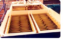
Inclined Plate Clarifier |
A reduction of the required floor space is
acquired by diminishing the separation between the horizontal plates to
a few inches and stacking the settling surfaces. Inclining the plates
to provide self flushing, 45º for heavy particles and 60º for light
particles, reduces the available horizontal projected area (effective
settling area) by a factor equivalent to the cosine of the angle. The
surface area diagram (below) graphically compares the floor space
requirements of an HEI inclined plate clarifier with the equivalent
horizontal projected settling area.
Settling Rate |
The settling rate for a specific solids should be
determined by standard laboratory tests. Light particles, such as metal
hydroxides, usually require a design parameter of 0.25 gallons per
minute per square foot of horizontal projected area. These low density
solids require the inclined plates to be set at a 60º angle to induce
the particles to slide down the plate. Heavier particles (such as sand
that easily flow) will readily slide from plates set at a 45º angle.
Maximum flow rate of an inclined plate clarifier
is based on the flow rate per unit of a horizontally projected surface
area. Retention time in the clarifier is not a design criteria.
However, attaining optimum performance requires the prudent design to
recognize several additional, very important factors.
Inlet Plenum |
An inlet plenum must be provided to uniformly
distribute the influent to the inclined plate compartments. Laminar
flow must be established as the flow enters the plate area. The
hydraulic momentum of the incoming liquid must be dissipated to prevent
channeling. The HEI design does not use orifices which may clog with
heavy suspended solids.
Outlet Area |
 The
outlet area must be designed to force uniform flow from all plate
compartments and also over the entire width of the plates. For example,
wide plates (4 foot and over) with side outlets do not utilize the
center section and must be proportionately decreased. A poorly designed
outlet can result in one 50-60% plate utilization. The HEI clarifier
utilizes an orifice type weir with orifices placed on each side of the
plate to force uniform flow from each compartment.
The
outlet area must be designed to force uniform flow from all plate
compartments and also over the entire width of the plates. For example,
wide plates (4 foot and over) with side outlets do not utilize the
center section and must be proportionately decreased. A poorly designed
outlet can result in one 50-60% plate utilization. The HEI clarifier
utilizes an orifice type weir with orifices placed on each side of the
plate to force uniform flow from each compartment.
Equalization Compartment |
The HEI inclined plate clarifier provides
equalized flow between two or more plate packs. After installation,
clarifiers will often settle which creates channeling and turbulence
through one of the plate packs. A prudent design prohibits channeling.
Solids Removal |
|
Solids sliding off the plates must be provided
with a sufficiently large compartment to insure adequate capacity for
the accumulated solids. Turbulence and channeling are avoided by
continuously removing the solids which will disrupt the flow pattern if
allowed to build up and contact the inclined plate.
 There
are essentially only two designs of sludge storage compartments in
general use. The conventional design is an inverted cone or pyramid
with angles to match the expected angle of repose of the solids to be
collected. There
are essentially only two designs of sludge storage compartments in
general use. The conventional design is an inverted cone or pyramid
with angles to match the expected angle of repose of the solids to be
collected.Due to the hydrostatic head present before and
during sludge removal, two adverse conditions tend to be created. The
sludge which accumulates between draw downs will compact, changing its
angle of repose. With the draw off pipe open the hydrostatic head will
cause the more fluid supernatent to create a channel (rat hole) from
the top sludge layer to the outlet. The result is too much liquid and
not enough sludge removed.
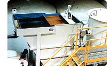
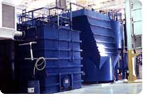
The preferred design is a compartment with almost
a flat bottom and a top driven motorized rake which will break up
compacted sludge and direct the sludge to the center discharge point
preventing the "rat hole" phenomenon. This design also allows for the
maximum amount of sludge storage below the plates for a given height
(three time as much as a cone bottom design). |
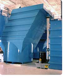
HEI Inclined Plate Clarifier with Motorized Sludge Rake |
Sludge Thickening |
 For
most applications there is insufficient volume below the inclined
plates to provide adequate storage time to attain sludge thickening or
compaction. A secondary tank is required to provide sufficient storage
time to accumulate and thicken the collected solids. Laboratory studies
must be performed on each sludge to determine thickening rate. Usually
sludges must be retained in non-turbulent condition for 4-24 hours to
reach an optimum concentration. A typical well-flocculated clarifier
influent may contain 300-500 ppm suspended solids. The solids will
settle to a volume of approximately 10% of the initial volume
(0.3-0.5%). Hence, a 10% underflow is required to remove the
accumulated solids. The sludge accumulator or sludge thickener must
have the capacity to store the accumulated solids for at least 24
hours. The filter press or other compaction device must be sufficiently
large to continuously compact the collected solids. Contact your HEI
technical representative to assist you in the sizing of your liquid
solids separation and solids compaction system.
For
most applications there is insufficient volume below the inclined
plates to provide adequate storage time to attain sludge thickening or
compaction. A secondary tank is required to provide sufficient storage
time to accumulate and thicken the collected solids. Laboratory studies
must be performed on each sludge to determine thickening rate. Usually
sludges must be retained in non-turbulent condition for 4-24 hours to
reach an optimum concentration. A typical well-flocculated clarifier
influent may contain 300-500 ppm suspended solids. The solids will
settle to a volume of approximately 10% of the initial volume
(0.3-0.5%). Hence, a 10% underflow is required to remove the
accumulated solids. The sludge accumulator or sludge thickener must
have the capacity to store the accumulated solids for at least 24
hours. The filter press or other compaction device must be sufficiently
large to continuously compact the collected solids. Contact your HEI
technical representative to assist you in the sizing of your liquid
solids separation and solids compaction system.
Construction |
HEI inclined plate clarifiers are constructed of
1/4" ASTM A36 structural carbon steel. The inclined plates are fiber
reinforced plastic with spacers and brackets fabricated of 304
stainless steel and polyvinyl chloride plastic. Units will be
fabricated entirely of stainless steel on request. All carbon steel
surfaces are media blasted to SSPC SP-6 finish and coated on the
interior with high build polyester epoxy and the exterior with acid
resistant epoxy. The units will be coated with FRP on request.
Manufacturing Specifications |
 |
|
Optional Equipment |
-
Flash mix & flocculate sections with mixers
-
Acid resistant FRP coating on interior and/or exterior
-
All stainless steel construction
-
Pumping systems
-
Automatic sludge removal system
-
Oil skimmers
-
Covers
-
Ladders and platforms
-
Seismic zone certification
Installed Dimensions HEI Inclined Plate Clarifier |
|
||||||||||||||||||||||||||||||||||||||||||||||||||||||||||||||||||||||||||||||||||||||||||||||||||||||||||||||||||||||||||||||||||||||||||||||||||||||||||||||||||||||||||||||||||||
NOTES:
-
HEI Model No. (110/60/SA) typically indicates: 110 sq. ft. horizontal projected area. 60 indicates the angle of inclination of the plates, "m" indicates motorized sludge rake, "s" indicates sloped bottom, A indicates the length of the settling plate, A is 30" long, B is 60" long, C is 120" long.
-
Flash mix and flocculation sections for 2,000 sq. ft. and greater size clarifiers are shipped separately.
-
Clarifiers supplied with 45° inclined plates will have 40% more horizontal projected area for the equivalent outside dimensions.
-
Dimensions given are approximate.
-
HEI will custom fabricate clarifiers to accommodate reduced floor space or ceiling heights.
-
Dimensions of units having 1,000 sq. ft. or less include flash floc sections.